
Configuring your RC-100 play clock system
With the academic year right around the corner, it’s a good time to touch upon a topic that we receive a lot of questions on. Many schools and universities use our play clock displays during their games. One of the most popular control options is the wireless RC-100 handheld controller. Setting up and installing the […]
Daktronics Control Panel on 7/13/2017
Categories: Pro Sports and Colleges
With the academic year right around the corner, it’s a good time to touch upon a topic that we receive a lot of questions on. Many schools and universities use our play clock displays during their games. One of the most popular control options is the wireless RC-100 handheld controller.
Setting up and installing the communication equipment and displays is an effortless process. However, the configuration of the communication system can take some time and knowledge to set up properly. To assist with this, use the guide below. Once you have all your base stations installed, follow the steps listed to configure and set up your RC-100 base stations and handheld.
1. Setting the Right Channel
The channel is a unique wireless address you assign to the base stations so they can communicate with each other and back to the RC-100 handheld. If you have other scoreboards in the area that use base stations, you will need to determine their channels as you do not want to use a channel that is already being used by another system. Regardless of the channel you go with, ensure both of your base stations are set to the same channel for the Delay of Game Clocks or Play Clocks.
To change the channel, access the base station and locate the dials. One is labeled “Channel” and the other “Function”. There is a slot in the dial that displays a number. Once this is located, change the dial to a predetermined channel on all base stations being used in this system.
2. Verifying the Function
All base stations should come pre-set on function 5 from the factory, but it is always a good idea to verify this before installing. If you are installing new base stations don’t worry about changing this off 5. However, if you are installing or working with older base stations, you may need to use function 2.
To verify if function 2 should be used, you will need to verify the generation of the base stand and handheld controller. To do this, follow DD2223959. Gen I base stations will show ED14906 Version 2.1 or lower and will use function 2.
To verify the generation of the handheld controller, power on the unit and boot up. The LCD display will show the firmware version. Gen I handheld controllers display ED14905 Version 1.6 or lower on the LCD screen at power up and use function 2.
3. Setting the Server
Once the dials are set we will need to select one base station that will be the server, and the second base station will then be the client.
Once the server has been designated, locate the 3-pin mode selector (labeled X1) near the dials. It should come defaulted to be set up as a server but you will want to verify it looks exactly how it is shown in figure 1.
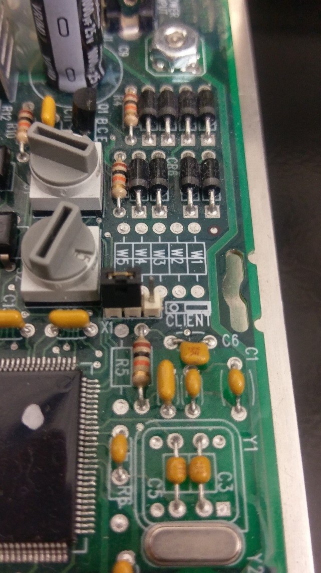
Figure 1 – Base Station set to server mode
4. Setting the Client(s)
Any other remaining base stations will then need to be set up to operate as a client. This will allow it to display the exact same information that the server unit is displaying.
On the client(s), you will need to move the black jumper on the 3-pin mode selector (X1) so it is operating as a client. Reference figure 2 on how it should look after you’ve accomplished this.
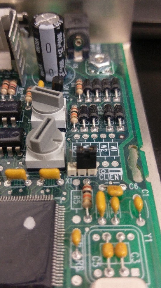
Figure 2 – Base station set to client mode
5. Other items to verify
Please follow this checklist to ensure all base stations have been installed for optimal operation:
- Verify that all antennas are pointing up and are parallel with each other.
- Verify that all antennas cables have been passed through the pre-drilled holes and tightened properly using the provided lock washer and nut.
- Verify there is a clear line of sight between all antennas.
- Use the provided adhesive Velcro to properly mount the base station.
*Do not lay the base station in the bottom of the timer as pooling water can cause water damage. - Ensure the antenna cable inside the timer is routed below the circuit board. This will prevent water damage if water gets through the antenna cable hole.
- Verify there is no damage, twists or knots on any cabling.
6. Handheld setup and communication test
Now that everything is set up inside the timers, power on the handheld. The first screen will ask what channel to set the handheld to. You can enter your pre-determined channel and press enter. It may ask if you want to modify the contrast, you can press cancel on this screen. Finally, it will ask for the code you want to use. If you are using this setup for timers, you will want to use code 05. Otherwise, reference the code listed on your sport insert.
For additional questions or assistance with your Daktronics equipment, visit http://www.daktronics.com/support.